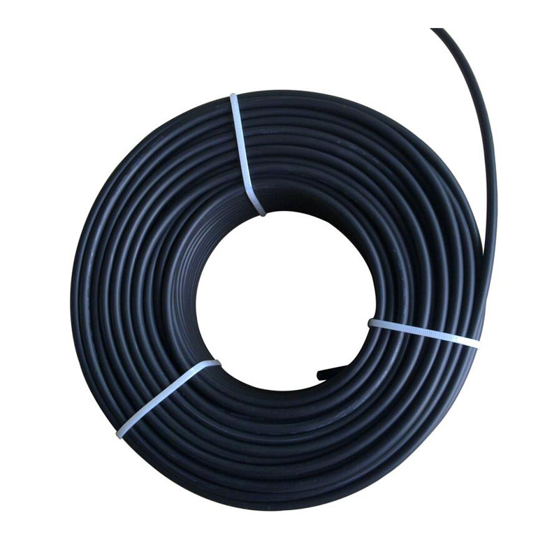
IEC 62930 Pure Tinned Copper PV Cable
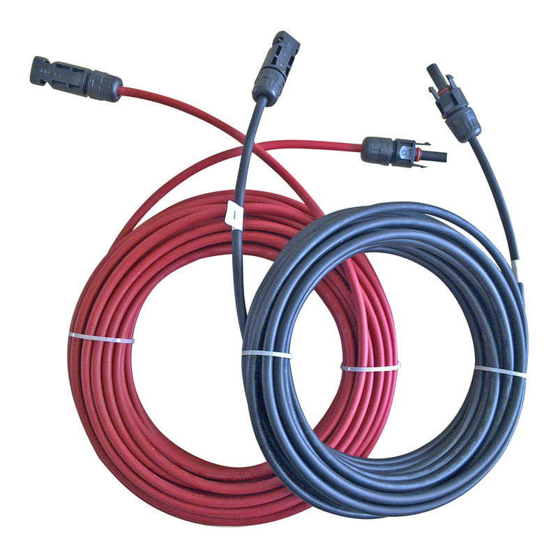
As a photovoltaic cable source manufacturer, in order to ensure product quality, SOWELLSOLAR follows the quality management system standard (IEC) in the production process and strictly controls each production line. IEC 62930 Pure Tinned Copper PV Cable has undergone a number of rigorous tests to ensure that the product can work properly under a variety of harsh conditions. Pure tinned PV cable is a kind of cable specially used in solar power generation system. It is mainly used to transmit the direct current generated by solar photovoltaic panels to inverters or other equipment for conversion into alternating current supply for domestic, industrial or commercial use.
Send Inquiry
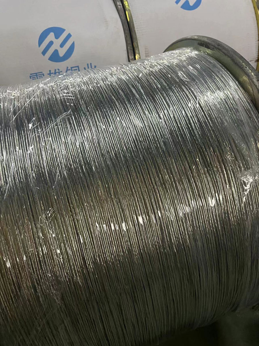
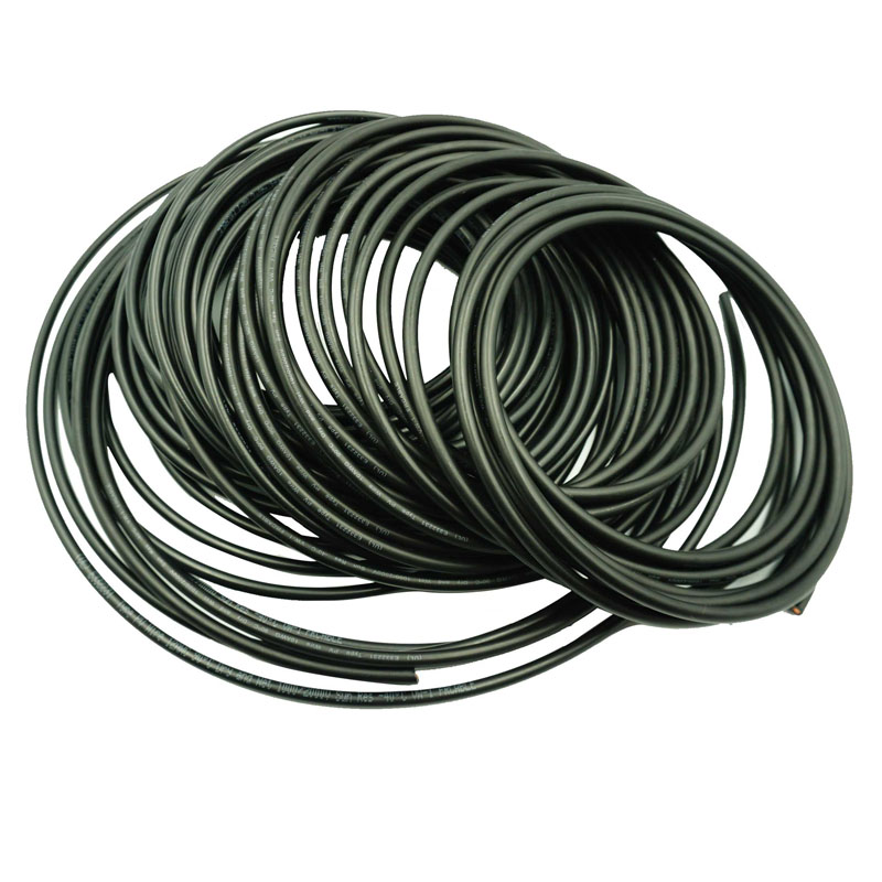
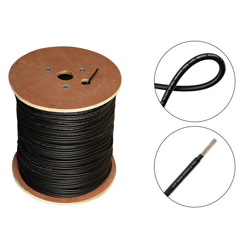
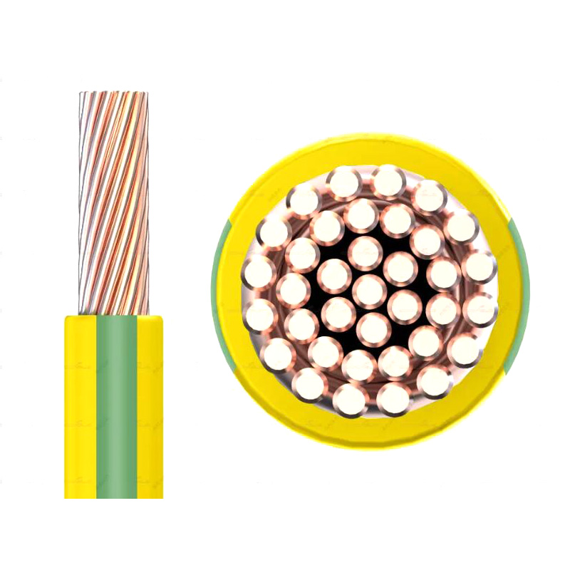
IEC 62930 Pure Tinned Copper PV Cable are usually composed of multi strand copper cable, Different model is different conductor cross section. 56 and 84 strand design number are common model, refer to 4mm² and 6mm². Our cable (Pure Tinned Copper PV Cable) has been specially designed and selected with high heat resistance, weather resistance and UV resistance to ensure long-term stable operation in outdoor environments.Tinned Copper PV Cable are installed between solar panels and connected to inverter. When the sun shines on the photovoltaic panels, they generate direct current, which is transmitted to the inverter via the photovoltaic cable. The inverter then converts DC to AC and supplies it to the equipment or network that needs to be used. We supply high-quality cable specially designed and manufactured to connect the various components of a solar power generation system and transmit DC/AC power.
EN50618 Current carrying capacity of cables specified in the standard
Table A.2 — Recommended use of cables for PV systems
| 1 | 2 | 3 |
| Construction | Recommended use | Comments |
| Cables for PV-systems H1Z2Z2-K |
Intended for use in PV installations e.g. acc. to HD 60364-7-712. They are intended for permanent use outdoor and indoor, for free movable, free hanging and fixed installation. Installation also in conduits and trunkings on, in or under plaster as well as in appliances. Suitable for the application in/at equipment with protective insulation (protection class II) They are inherently short-circuit and earth fault proof acc. to HD 60364-5-52. |
For recommended bending radii see EN 50565-1:2014, Table 3 Max. storage temperature: + 40 ℃ Min. temperature for installation and handling: - 25 ℃ |
Table A.3 — Current carrying spacity of PV cables
|
Nominal cross sectional area
mm2
|
Current carrying capacity according to method of installation | ||
|
Single cable free in air
A
|
Single cable on a surface
A
|
Two loaded cables touching, on a surface
A
|
|
| 1,5 | 30 | 29 | 24 |
| 2,5 | 41 | 39 | 33 |
| 4 | 55 | 52 | 44 |
| 6 | 70 | 67 | 57 |
| 10 | 98 | 93 | 79 |
| 16 | 132 | 125 | 107 |
| 25 | 176 | 167 | 142 |
| 35 | 218 | 207 | 176 |
| 50 | 276 | 262 | 221 |
| 70 | 347 | 330 | 278 |
| 95 | 416 | 395 | 333 |
| 120 | 488 | 464 | 390 |
| 150 | 566 | 538 | 453 |
| 185 | 644 | 612 | 515 |
| 240 | 775 | 736 | 620 |
| Ambient temperature: 60 ℃ (see Table A.4 for other ambient temperatures) max. conductor temperature: 120 ℃. | |||
| NOTE The expected period of use at a max. conductor temperature of 120 ℃ and at a max. ambient temperature of 90 ℃ is limited to 20 000 h. | |||
